This project guides you through building a cost-effective and versatile DIY IoT energy meter using readily available components. We'll leverage the power of the ESP8266 NodeMCU, the accuracy of an INA219 current sensor, and the convenience of the Blynk IoT platform to create a system capable of monitoring voltage, current, power, and energy consumption. The project is designed for ease of assembly, utilizing a simple breadboard setup and straightforward wiring. Real-time feedback is provided via a 0.96-inch I2C OLED display, aiding in both debugging and monitoring.This tutorial provides a step-by-step guide, covering everything from assembling the hardware and verifying sensor functionality to setting up the Blynk application for remote monitoring. You'll learn how to integrate the INA219 sensor with the ESP8266, utilize the Blynk platform for data visualization and remote access, and configure widgets to display key energy consumption parameters. By the end of this project, you will have a functional, remotely accessible energy meter suitable for monitoring various DC devices, allowing for efficient energy management and cost tracking.
Pros And Cons
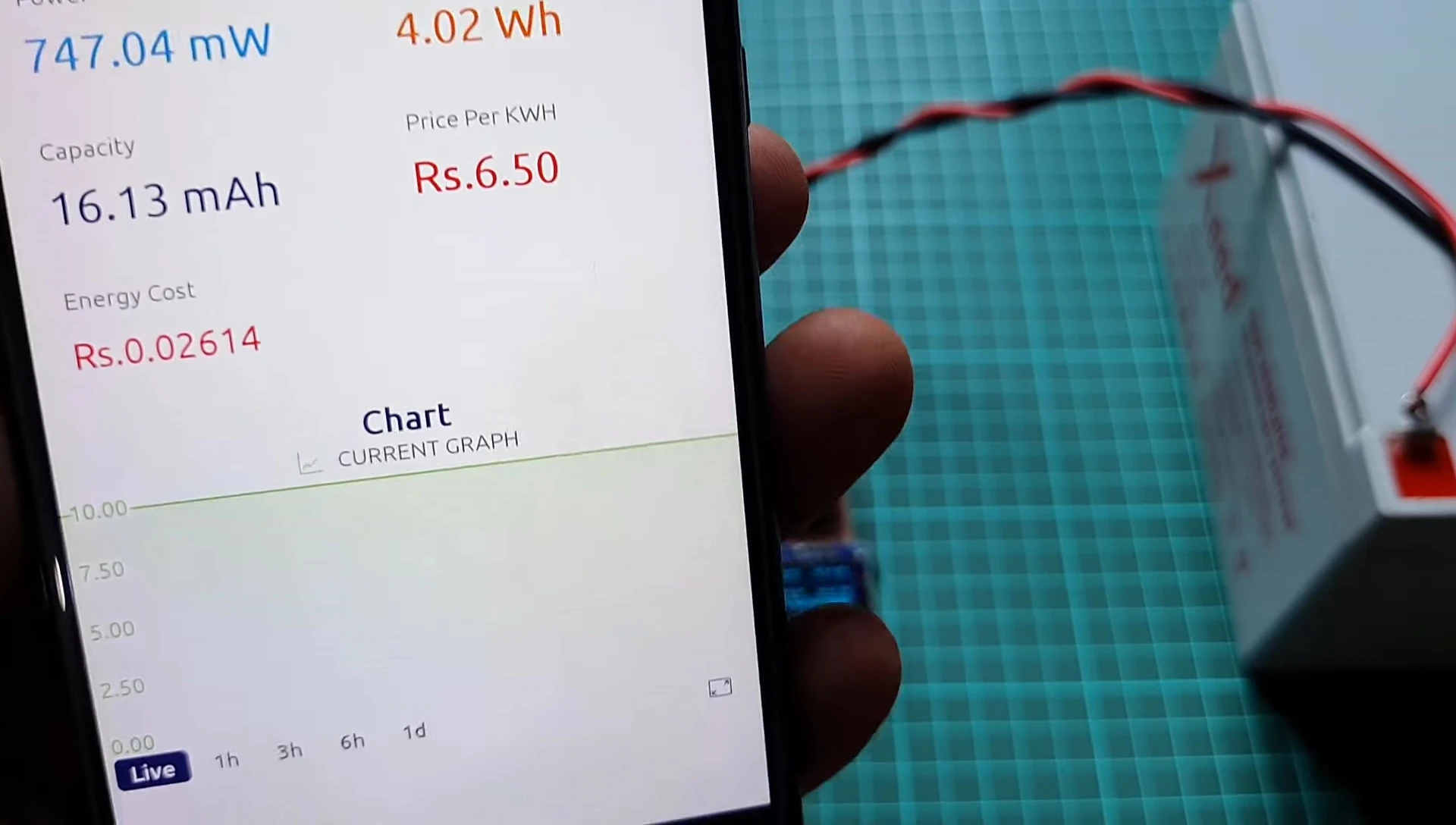
- Measures voltage, current, power, energy capacity, and energy cost.
- Monitors data on a 0.96" OLED display and the Blink 2.0 IoT platform.
- Suitable for measuring battery capacity of batteries or power banks.
- Measures voltage from 0 to 26V and a maximum current of 3.2A.
- Pocket-sized and portable.
Read more: AMI Meter Reading Guide: Understanding Your Smart Electricity Meter
Hardware Components and Wiring
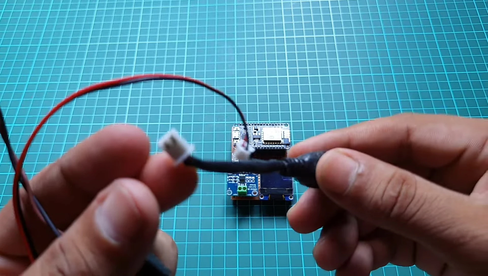
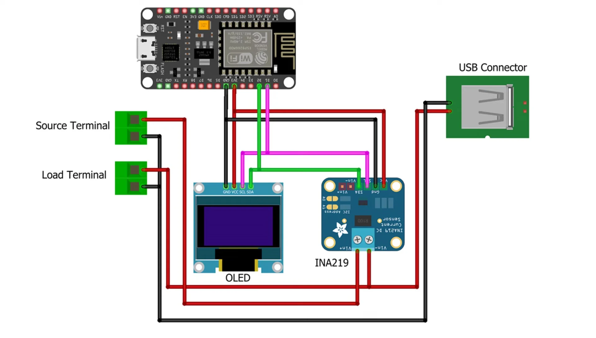
This project utilizes readily available components for easy assembly. The core components include an ESP8266 NodeMCU, an INA219 current sensor, a 0.96-inch I2C OLED display, and jumper wires. A breadboard facilitates easy prototyping and connection management.

Wiring is straightforward, connecting the INA219 to the ESP8266 via I2C. The INA219 can be powered by either 3.3V or 5V; in this example, 3.3V was used. Ensure proper connection of the clock (SCL) and data (SDA) lines for I2C communication.
Circuit Setup and Testing
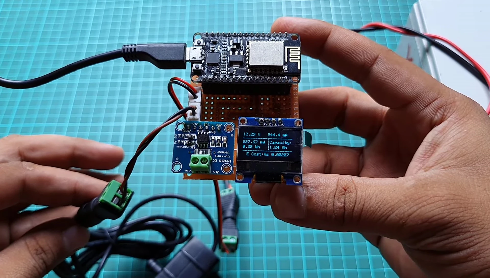
A simple test circuit was used to verify the INA219 functionality. A 12V battery served as the power source, and a 12V solenoid acted as the load. This setup allowed for monitoring changes in voltage, current, power, energy, and capacity.
The 0.96-inch OLED display provides real-time feedback on measured parameters. This makes debugging and verification during the development process much easier.
Blynk IoT Platform Setup
Blynk's cloud-based platform simplifies data visualization and remote monitoring. Create a Blynk account or log in if you already have one. Create a new template, naming it accordingly (e.g., "IoT Energy Meter") and selecting ESP8266 as the hardware.
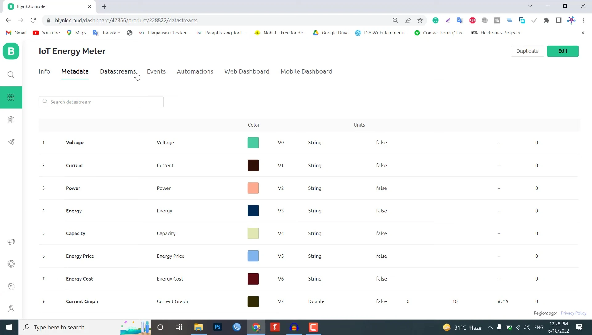
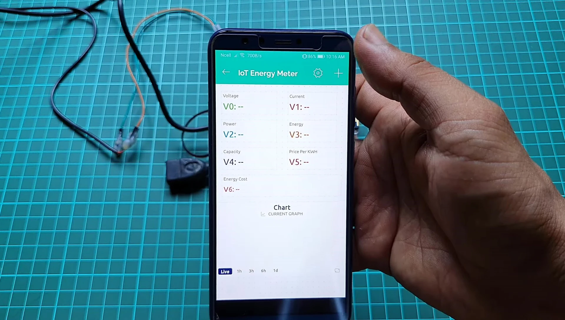
Create data streams within the template to represent the measured parameters (voltage, current, power, energy, capacity, cost, etc.). Assign virtual pins (V0-V7) to each data stream. The data type should be a string, except for a potential graph stream that may require an integer type.
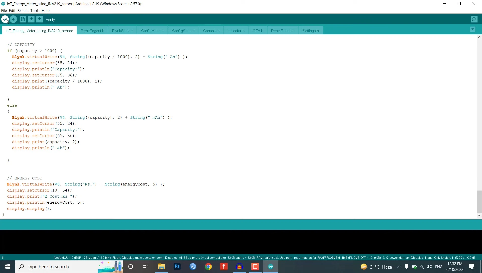
Programming and Code Upload
Ensure necessary libraries (Blynk library, SSD1306, INA219) are installed within your Arduino IDE. Before uploading the code, replace placeholders with your Blynk template ID and device ID.
Compile and upload the code to your NodeMCU. After a successful upload, the device will connect to your Wi-Fi network (provided the correct credentials are entered in the code).
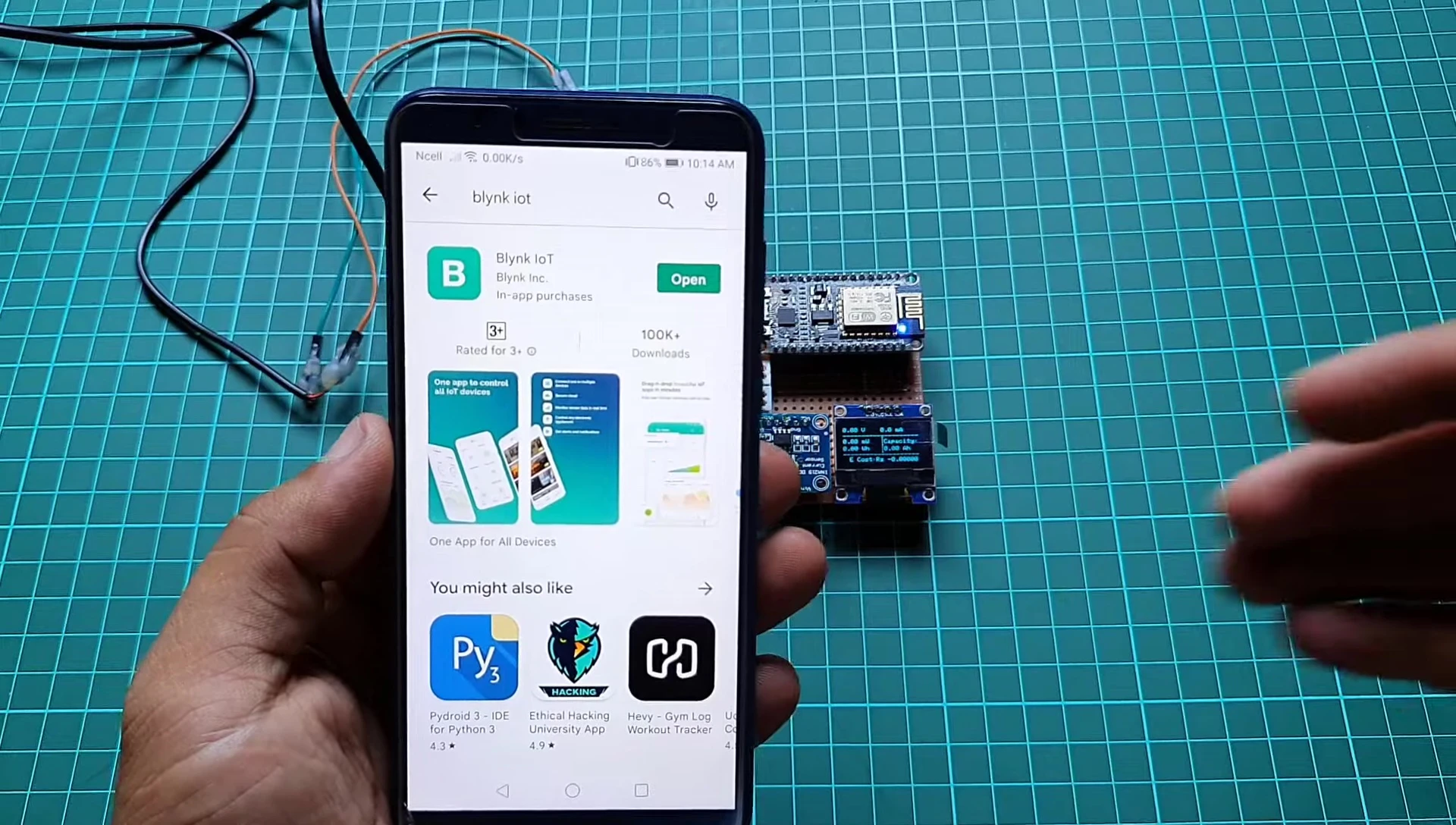
Blynk App Configuration and Monitoring
Download and install the Blynk app on your smartphone. Log in to your account, enable developer mode, and add a new device. Select the Wi-Fi network created by the NodeMCU and provide your router's credentials.
Add widgets to the Blynk dashboard (value displays and charts) and configure them to display data from the corresponding data streams. Once everything is set up correctly, you can monitor the energy meter readings remotely through the Blynk app.
Conclusion and Evaluation
This project successfully demonstrates a compact, IoT-enabled energy meter. The INA219 sensor provides accurate measurements of voltage, current, power, and energy. The ESP8266 facilitates wireless communication, and the Blynk platform allows for remote data monitoring.
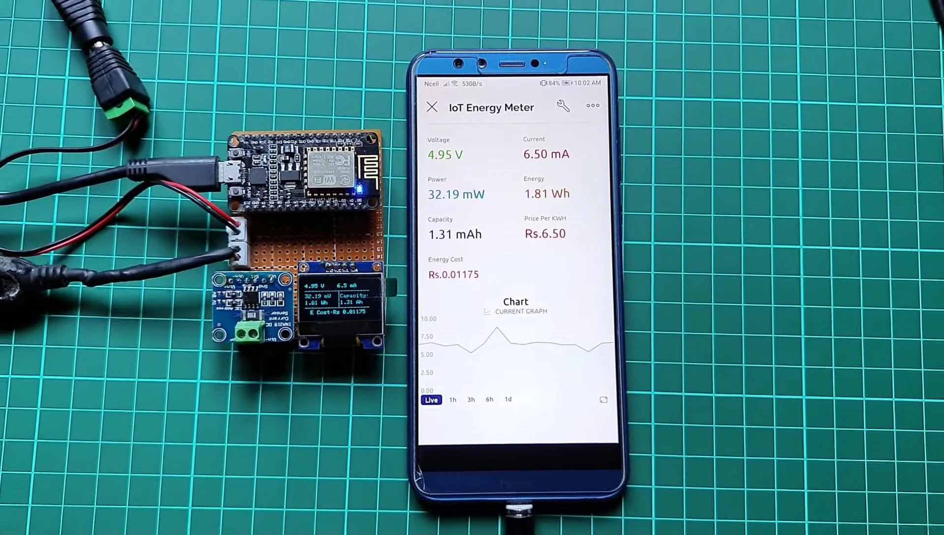
The project's accuracy was verified using a multimeter, showing satisfactory results. The OLED display provides real-time local feedback. This DIY solution offers a cost-effective and versatile way to monitor energy consumption for various DC devices.