This project details the construction of a smart Arduino-based power meter, a DIY solution for monitoring energy consumption and providing over/under voltage protection. Using readily available and relatively inexpensive components, this guide walks you through building a device capable of accurately measuring AC voltage and current. The core components include the ZMPT101B voltage sensor, the SCT-013 current transformer for non-invasive current measurement, and an Arduino Nano for processing and control. A 20x4 LCD provides a clear real-time display of power readings.The project offers a comprehensive tutorial, complete with circuit diagrams, code examples, and detailed instructions for assembly and calibration. The guide emphasizes safety precautions, particularly when working with mains voltage. Testing procedures are outlined to verify accuracy, and suggestions for miniaturization using a PCB and a smaller LCD are provided. This project is ideal for electronics enthusiasts looking to build a functional and informative energy monitor for their home or workshop.
Pros And Cons
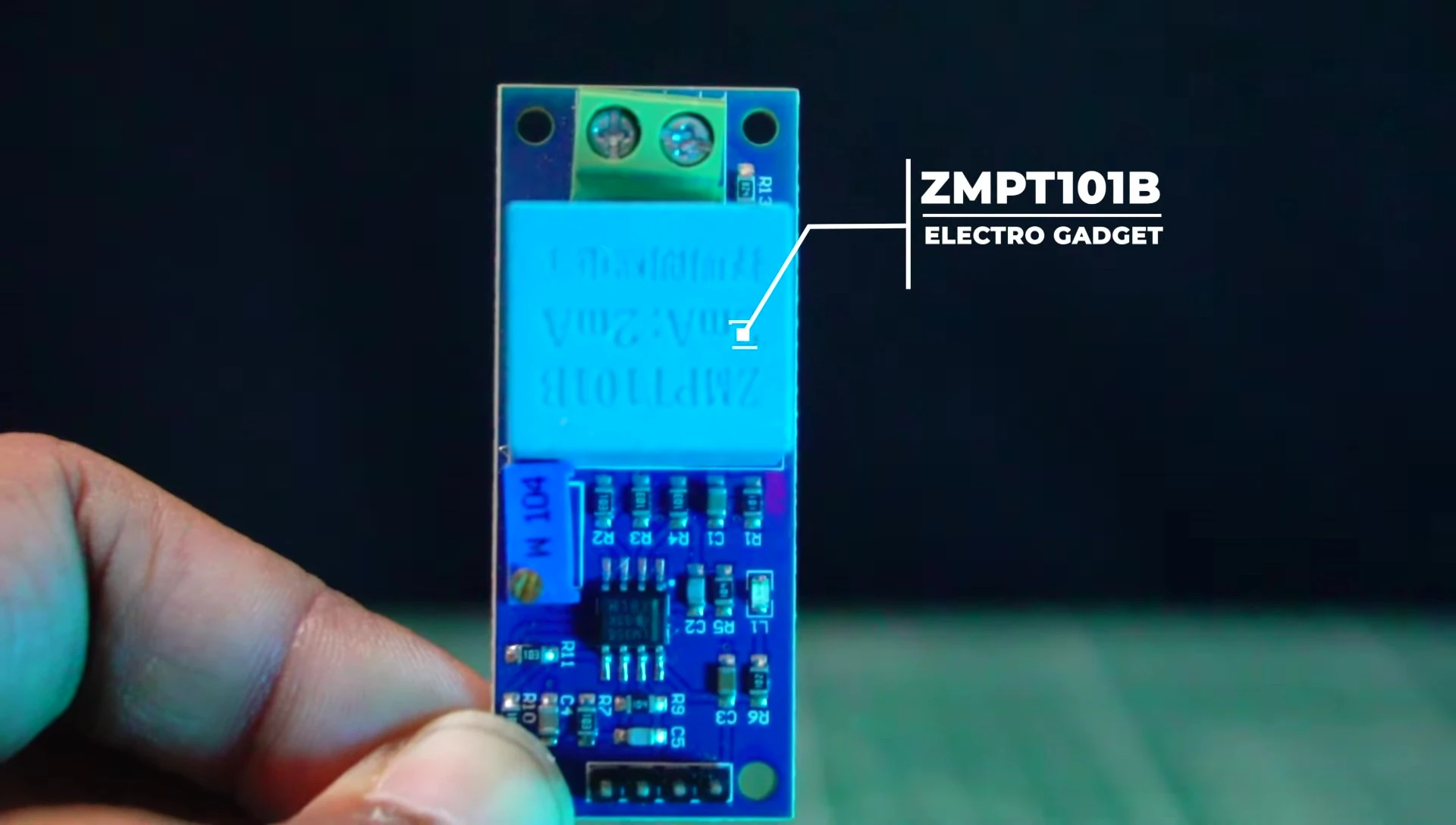
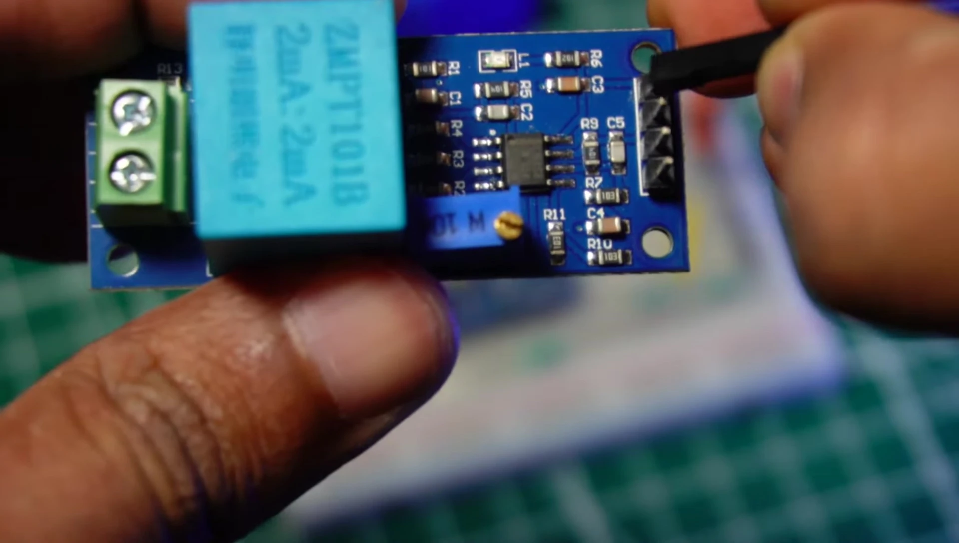
- High precision voltage transformer
- Easy to monitor AC mains voltage up to 1000 volts
- Communicates using I2C protocol
- Displays text and information
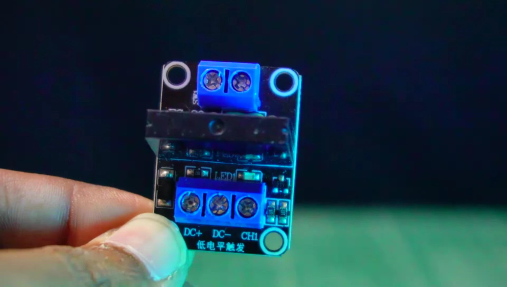
- Single channel
- Works with 5V DC trigger voltage
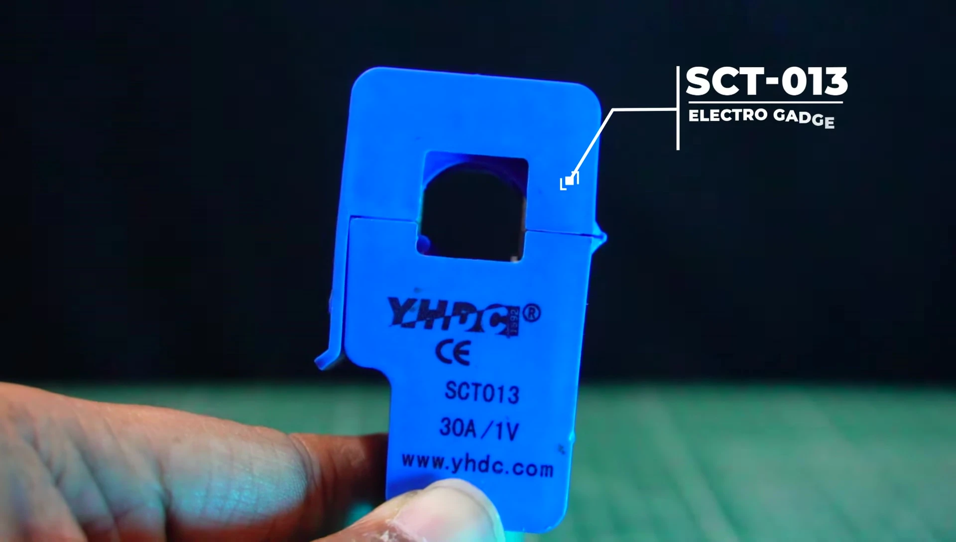
- Non-invasive
- Measures up to 30 amps
- Allows calculation of current
- Output voltage needs a voltage divider (210k resistor) and current limiting to prevent damage.
Read more: AMI Meter Reading Guide: Understanding Your Smart Electricity Meter
Components Overview
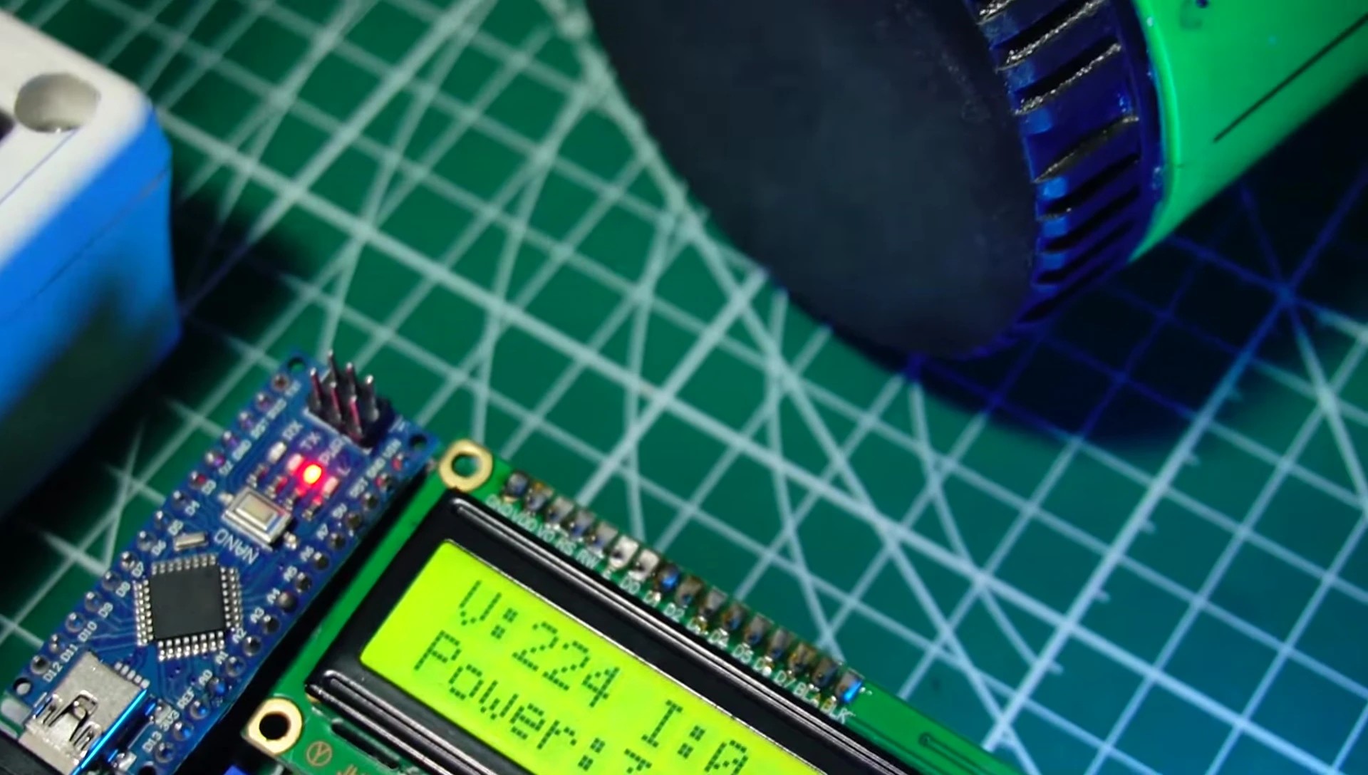
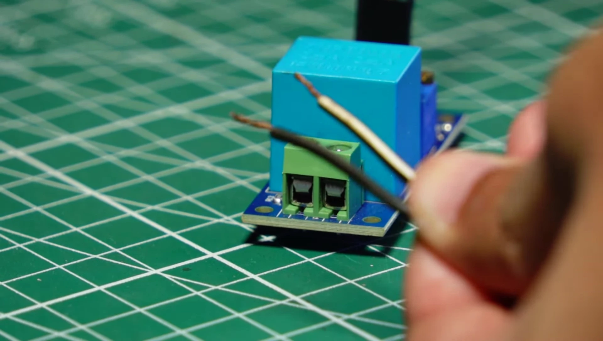
This project utilizes several key components to create a functional smart power meter. The ZMPT101B voltage sensor provides precise AC voltage measurement up to 1000V. The SCT-013 current sensor non-invasively measures current up to 30 amps, crucial for calculating energy consumption. A 20x4 LCD display shows real-time power readings, and a 5V relay module enables over/under voltage protection.
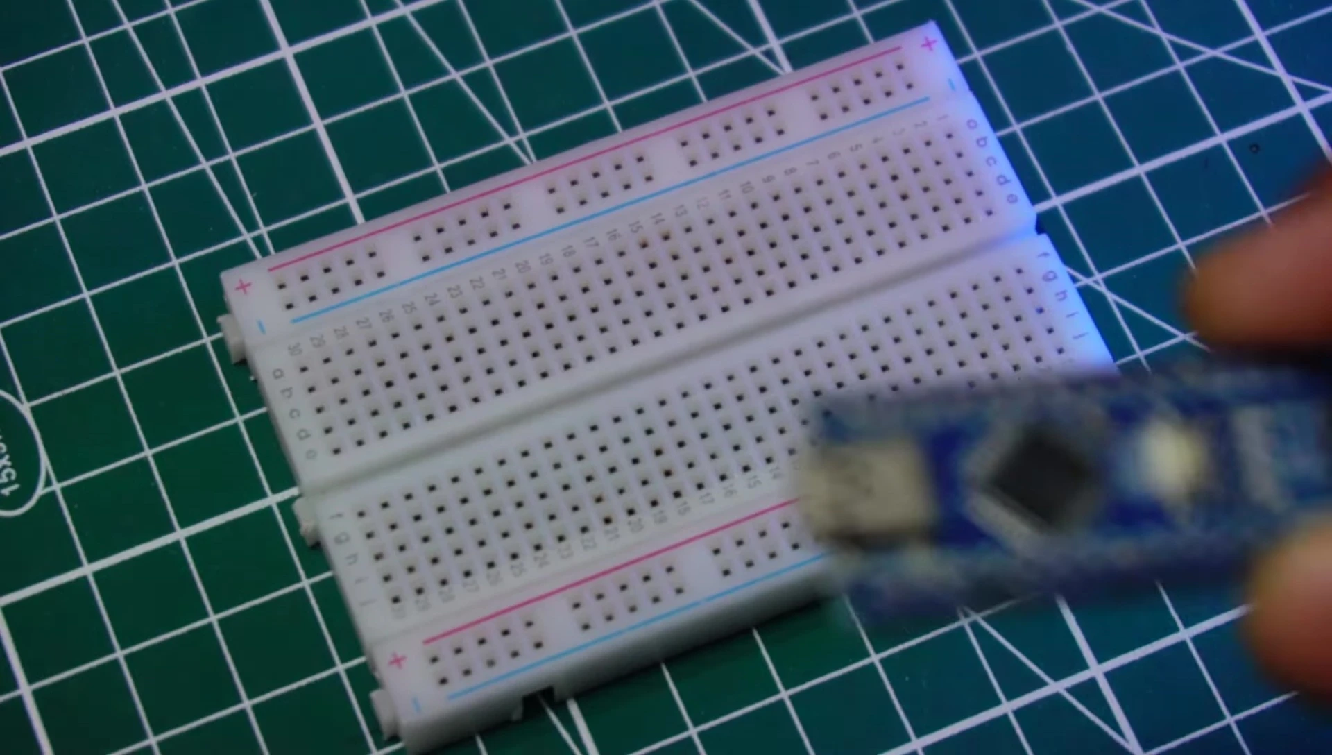
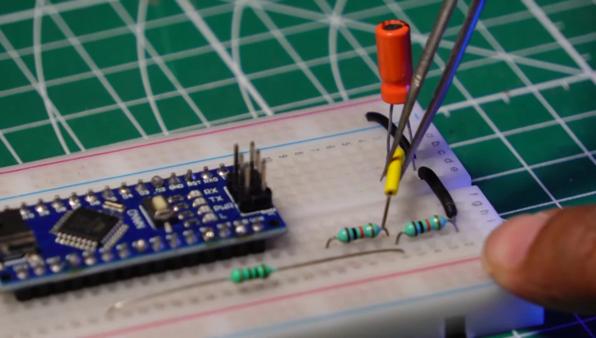
The Arduino Nano acts as the central processing unit, handling data acquisition and relay control. Supporting components include resistors (100Ω, 210kΩ), a capacitor (110µF, 25V), jumper wires, and a breadboard for easy assembly. Optional components such as DC jacks and a PCB board enhance the project's aesthetics and compactness.

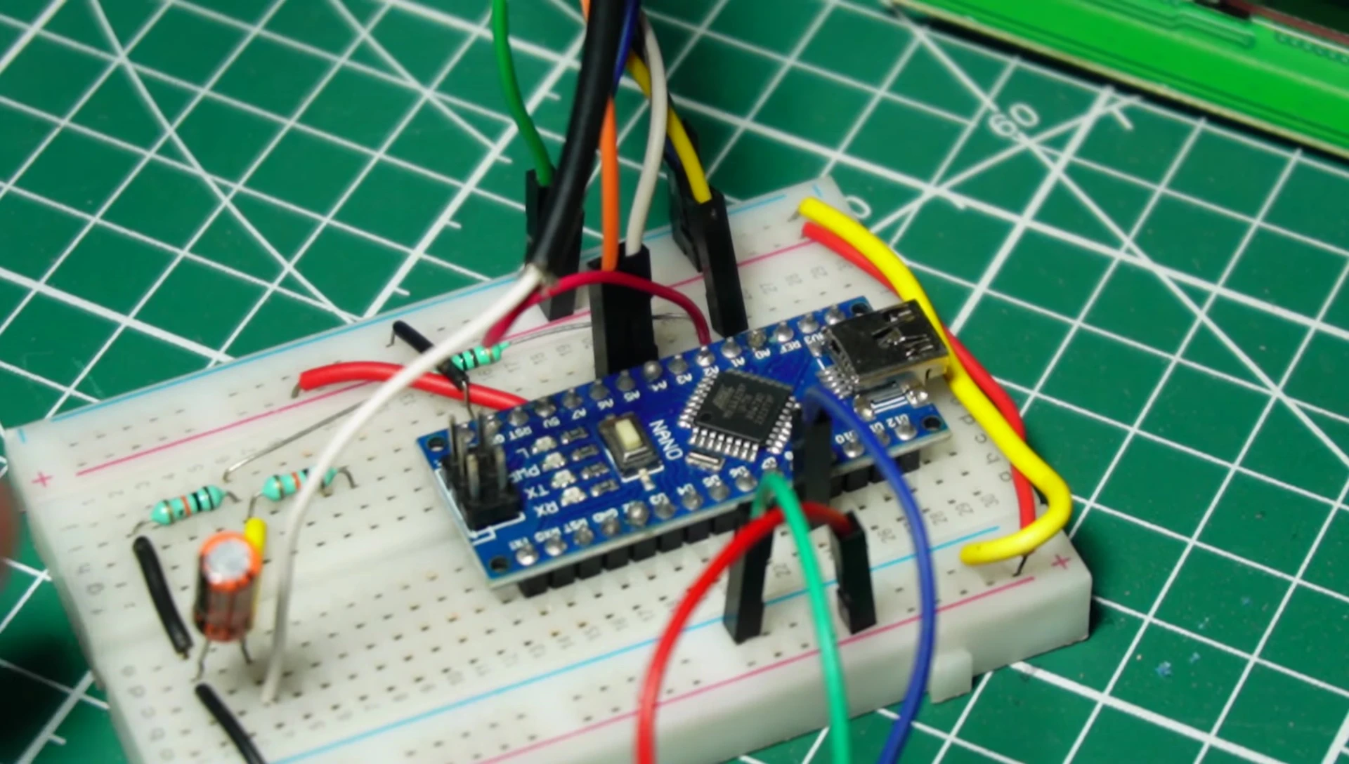
Circuit Connections and Explanation
The Arduino Nano is the heart of the system, connected to all other components via jumper wires on a breadboard. A 210kΩ resistor and a 100Ω resistor are crucial for voltage division and current sensing with the SCT-013, ensuring accurate and safe measurements. The 110µF capacitor filters out high-frequency noise to improve sensor stability.
The ZMPT101B voltage sensor's VCC, ground, and data pin are connected to the breadboard and Arduino. The 20x4 LCD and I2C module connect through their respective pins, providing a clear display of power data. The relay module's control pin is linked to the Arduino, enabling power switching based on voltage thresholds.

AC Power Connection and Safety
Connecting the AC power source requires careful attention to safety. The live and neutral wires from the 230V AC supply are directly connected to the voltage sensor. The SCT-013 current sensor clamps around a single AC wire carrying the load's current, allowing for non-invasive current measurement.
The relay module controls the connection to the load, providing over/under voltage protection. One end of the cut live wire is connected to the relay's common terminal, the other to the normally open terminal, which is then connected to the load. The load's other end connects to the neutral wire. Always prioritize safety when working with mains voltage.

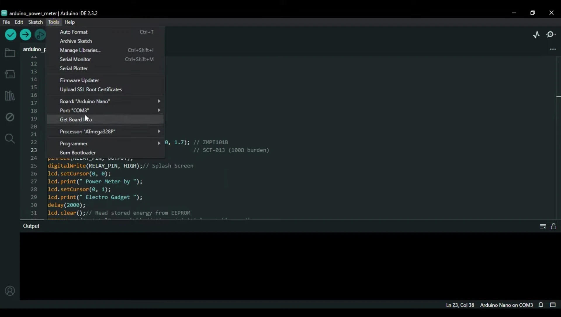
Software and Calibration
The Arduino code initializes the I2C LCD display and handles data acquisition. Calibration factors for voltage and current must be adjusted until the desired output is achieved; instructions are available in the project links. The code uploads to the Arduino Nano via USB, after selecting the correct board and port in the Arduino IDE.
The project's compactness can be further enhanced by using a double-sided PCB board and potentially a 16x2 LCD for a smaller footprint. Code and circuit diagrams are available on the project's website, making it easy to replicate this DIY project.
Testing and Conclusion
Testing is crucial for verifying the power meter's accuracy. The video demonstrates testing with a 12W LED bulb and a high-wattage heat gun, comparing the meter readings to a multimeter. The voltage sensor's accuracy is verified, as the readings match. The power meter accurately displays wattage.

This DIY smart power meter provides a cost-effective way to monitor energy consumption and incorporates over/under voltage protection. The project is well-explained, making it suitable for hobbyists with some electronics experience. The detailed instructions and readily available code and circuit diagrams contribute to its accessibility and buildability.