This comprehensive guide details the installation process for the Solax X3-Hybrid G4 and Chint DTSU666 smart meter, providing a step-by-step walkthrough for a successful integration. The guide emphasizes the importance of careful preparation, accurate wiring, and thorough verification at each stage to ensure optimal functionality and safety. From initial unpacking and component verification to final system checks, the instructions aim to equip installers with the necessary knowledge to complete the installation efficiently and effectively.The guide covers crucial aspects such as network cable connection, proper wiring of live and neutral wires to both the meter and inverter, correct connection of current transformers (CTs) for the DTSU666 meter, and configuring essential meter settings including baud rate, current transfer ratio, and meter address. It also highlights the importance of consulting the relevant manuals and seeking assistance from authorized Solax installers when needed. Following these instructions will help minimize installation errors and ensure the system operates as intended.
Read more: AMI Meter Reading Guide: Understanding Your Smart Electricity Meter
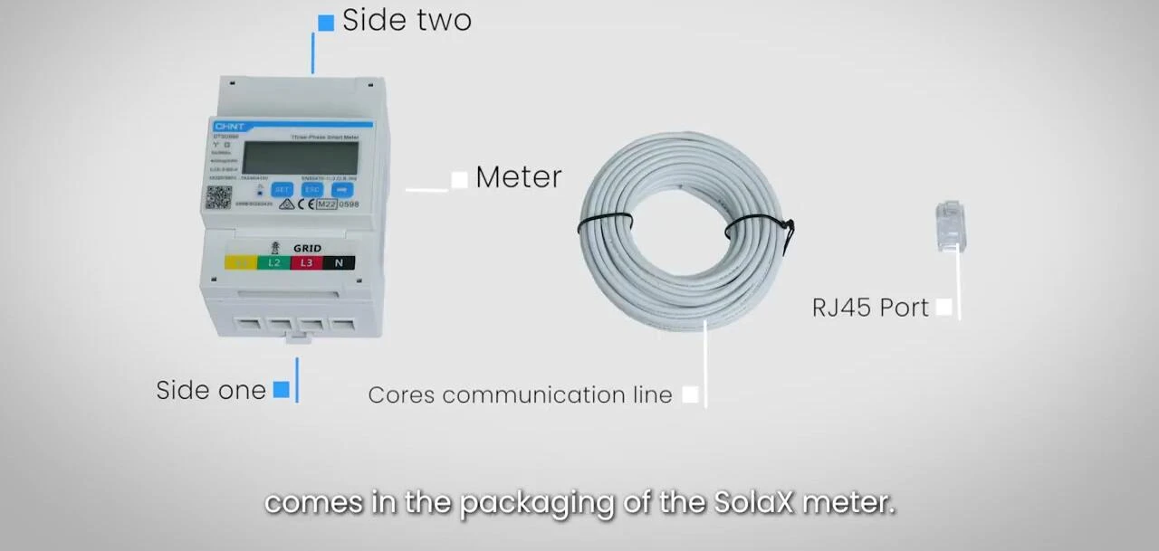
Unboxing and Package Contents
Before commencing the installation, carefully unpack the Solax smart meter and review the included components. Ensure that all parts listed in the manual are present and accounted for. This will help avoid any delays during the installation process. Familiarize yourself with each component's purpose and functionality before proceeding.
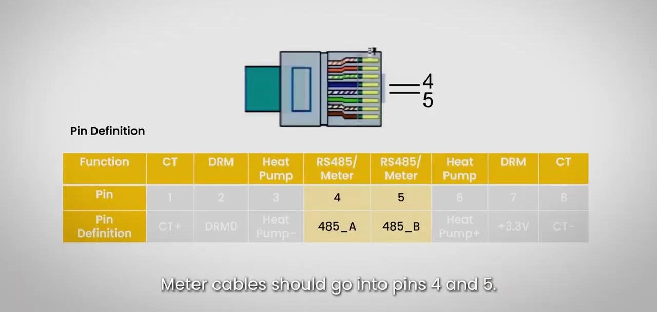
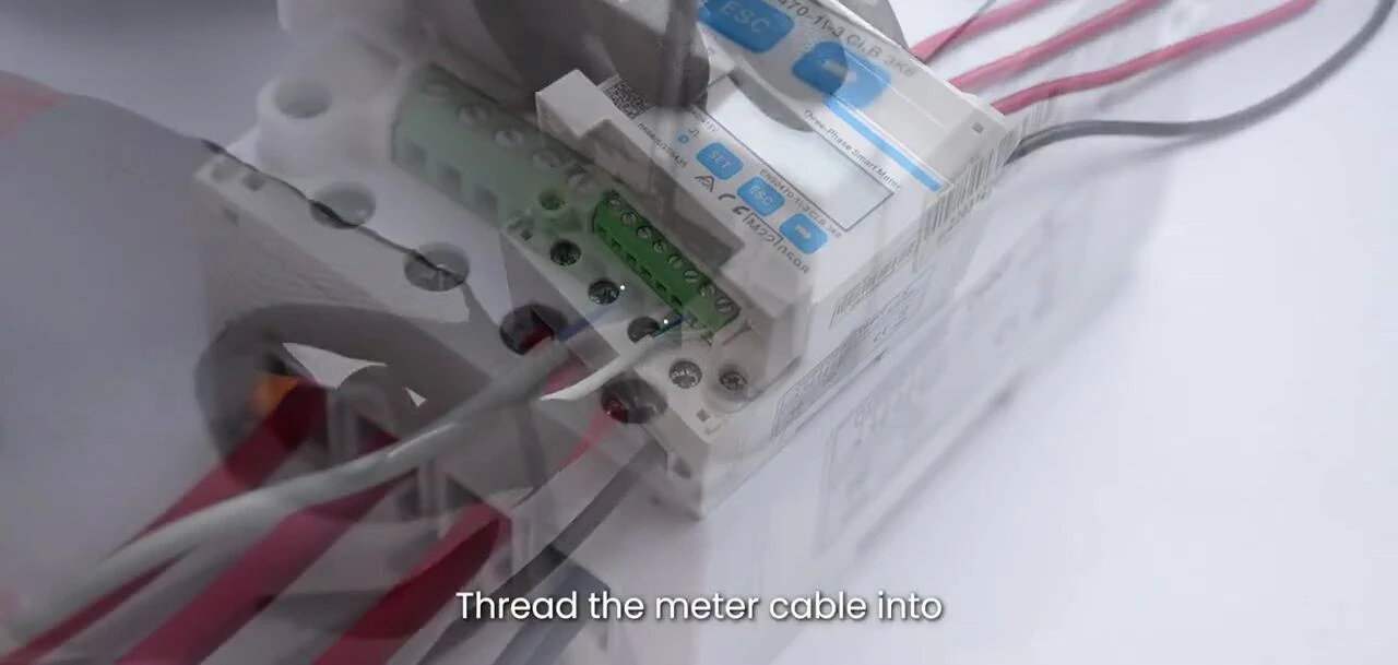
Wiring the Meter: Connecting the Network Cable
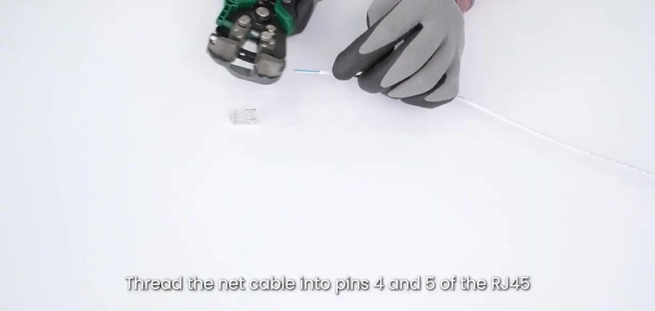
Connect the network cable to the designated pins on the RJ45 connector. It's crucial to correctly insert the cable into pins four and five to ensure proper network communication. Once correctly positioned, crimp the connection securely to prevent signal loss or interference.
Take your time and double-check the cable placement to ensure a secure connection. A faulty connection can cause significant issues with data transfer and meter functionality. Use appropriate crimping tools and follow the manufacturer's guidelines for a reliable crimp.
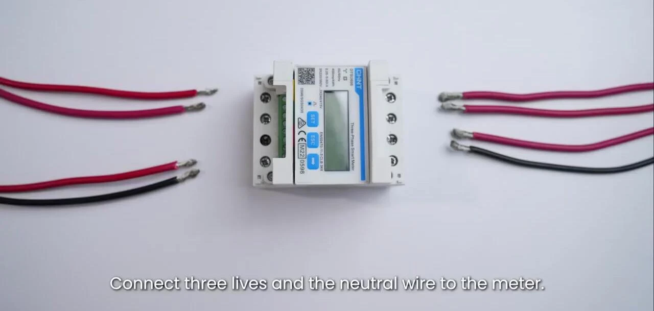
Meter Wiring: Connecting Mains and Inverter
Connect the three live wires and the neutral wire to the meter's designated terminals. Securely fasten the connections to prevent loose wiring. Always ensure that the power is switched off before making any connections to the mains supply.
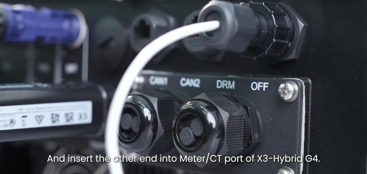
Next, connect the inverter end of the cabling to the meter's corresponding terminals. Again, double-check all connections to avoid potential electrical hazards or malfunction. Refer to the wiring diagram in your meter manual for accurate terminal identification.
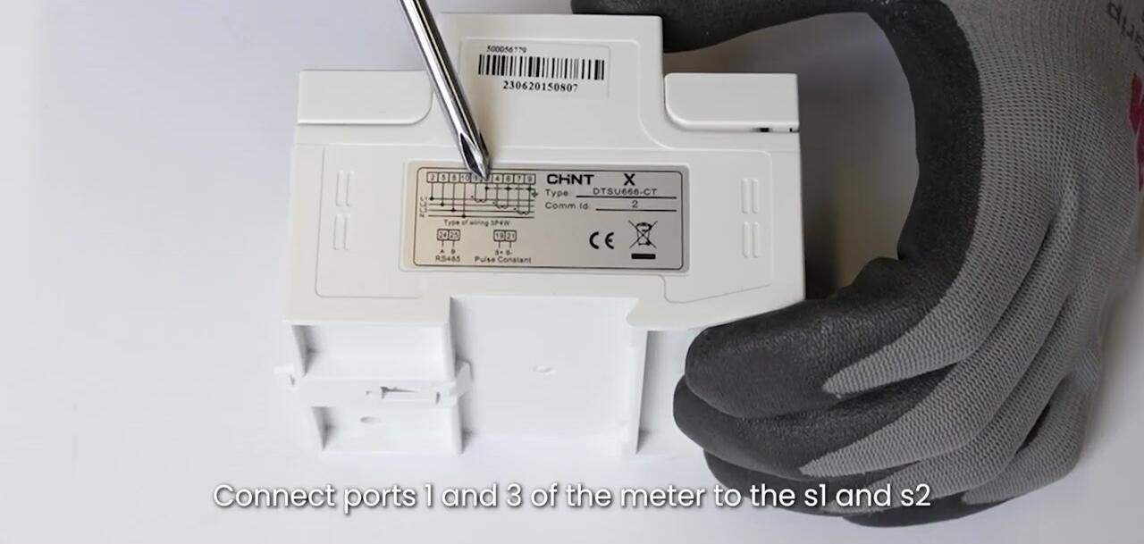
CT Connection for DTSU666 CT Meter
For the DTSU666 CT meter, connect ports one and three of the meter to the S1 and S2 of the first CT. Repeat this process for the remaining CTs, connecting ports four and six, and seven and nine, respectively. Ensure all connections are secure.
This step is critical for accurate current measurement. Ensure that the CTs are correctly clamped around the live cables, paying close attention to the direction indicated. Incorrect CT placement can lead to inaccurate readings.
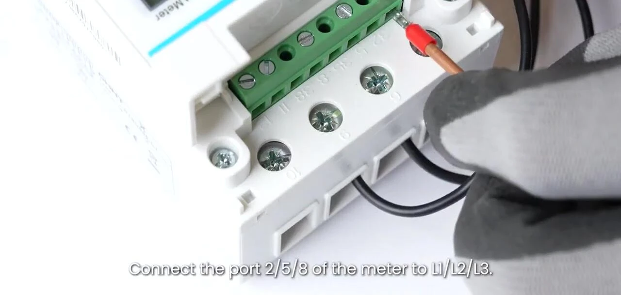
Final Wiring and Meter Setup
Connect the remaining terminals according to the wiring diagram. Securely connect port 258 of the meter to L1, L2, and L3. Connect port 10 to the neutral wire. Double-check all connections before powering the system.
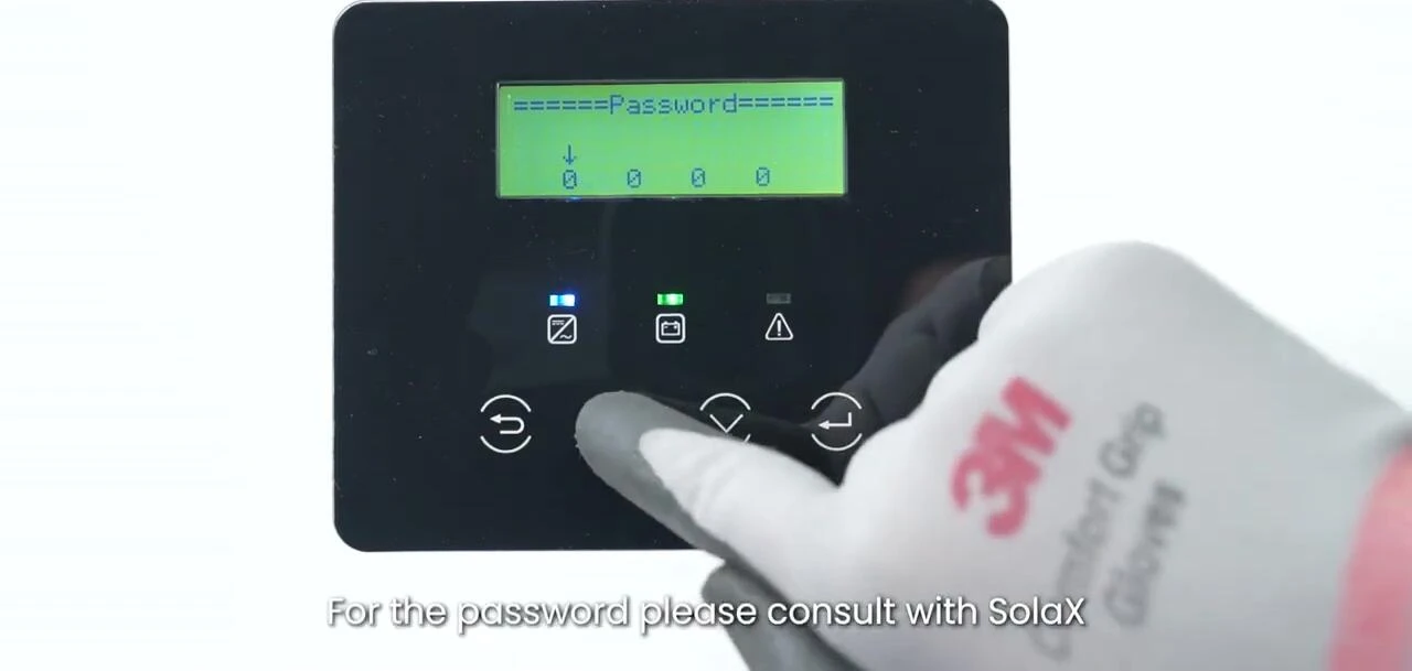
Consult the Solax authorized installers for the password required to access the meter's configuration settings. This password will be needed to proceed with the meter's setup and configuration.
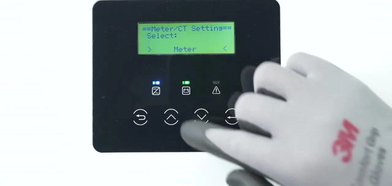
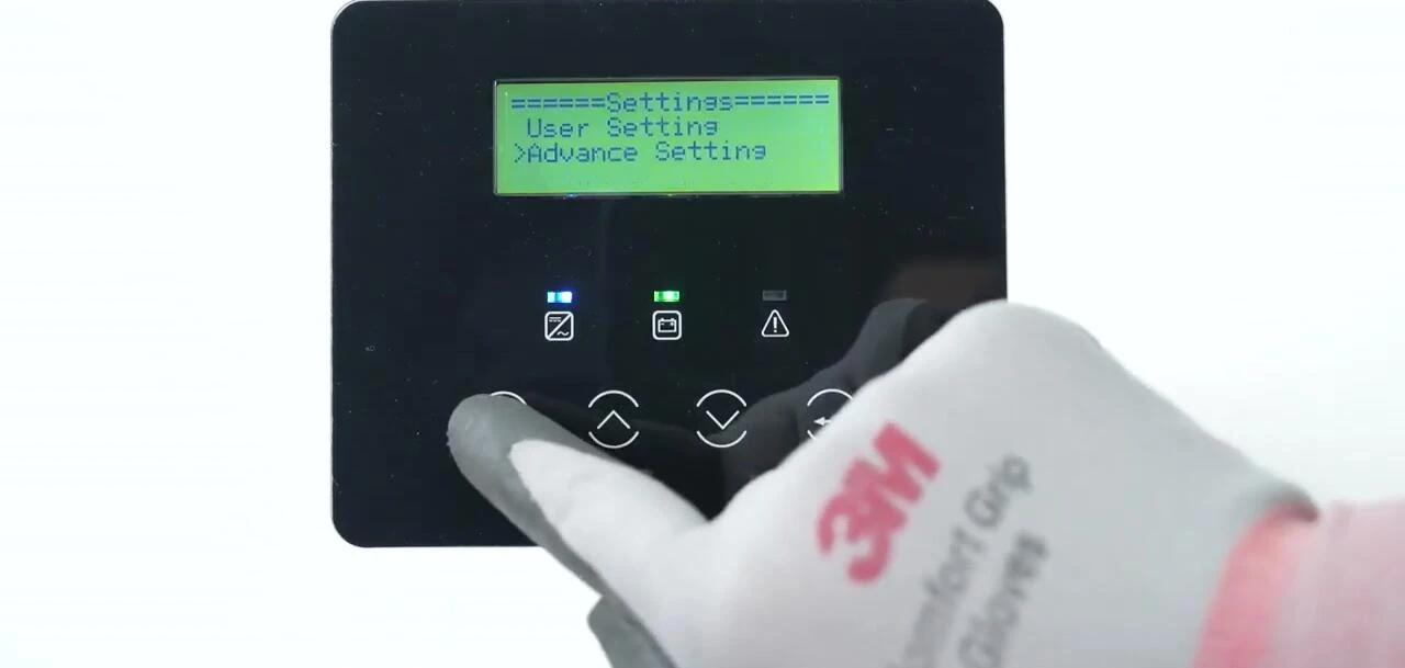
Meter Configuration and Settings
Enable the meter function and set the meter address within the configuration settings. Set the user value to zero if a zero injection requirement is in place. This ensures the meter is properly configured within the system.
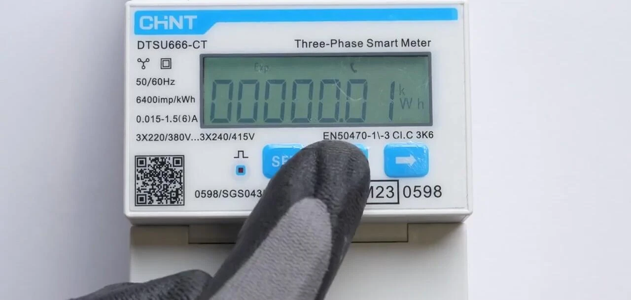
For the DTSU666CT meter, set the baud rate to 9600. Set the current transfer ratio (for example, to 40) and other parameters according to the instructions provided. Consult your manual for specifics on this model.
Post-Installation Verification
After completing the settings, verify the baud value, electric current, power, and power factor. Ensure that these readings match the inverter's output. This final step is essential to ensure the meter is functioning correctly.
This comprehensive installation guide ensures a seamless setup of the Solax X3-Hybrid G4 and Chint DTSU666 smart meter. Remember to consult the relevant manuals for detailed instructions specific to your system and always prioritize safety during the installation.